|
Recently we had the privilege of inspecting the start of a new Zero Energy home. This home is being built by Susquehanna Valley Builders in Harrisburg, PA. Energy Auditors helps ensure compliance with the the ZERH program requirements. PPL Electric is sponsoring the pilot program: PPL High Performance Homes Pilot.  Flying foundation Superior walls are shipped to the site and placed with a crane. 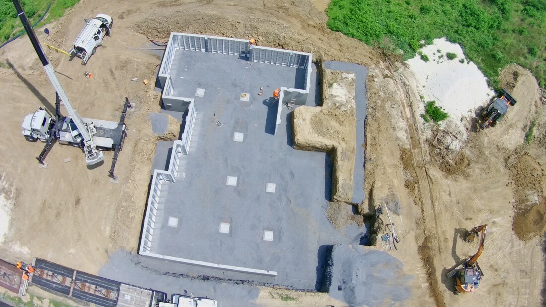 Bird's Eye view of the home
0 Comments
Kevin is pictured here with James and Chase from Alden Homes. We enjoyed partnering with them recently on their Zero Energy Model Home.  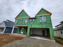 Energy Auditors has been proud to participate with Alden Homes (aldenhomes.com), PPL Electric and others in building a Zero Energy Ready home. PPL Electric Utilities is sponsoring a program to assist builders in building these high-performance homes. This Zero Energy Ready home was carefully inspected by Energy Auditors to ensure that it meets the stringent regulations of this program. These requirements include low energy usage, water conservation and indoor air quality. Our friends at Healthy Energy Pros provided the air seal package to ensure a very tight home. AeroBarrier is a relatively new, and quite fascinating process for sealing homes. This is a key component for energy savings and air quality. Read more on the Healthy Energy Pros website. Links to more information: PPL High Performance Homes Pilot Alden Homes Pilot Home Handout Healthy Energy Pros 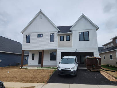 Is my home "leaking" electricity? We sometimes get questions from people who believe their home is "leaking" electricity. Of course, usage of electricity is normal. "Leakage" could be defined by the abnormal or unwanted usage of electricity. This article intends to serve as an introduction to a rather complex topic. In most cases you will want to consult an electrician if you suspect electrical leakage. Leakage Current to Ground On any electrical circuit, some current will escape the circuit and flow to ground. For example, a small amount of current will flow through the insulation on the conductors. Leakage current can cause unnecessary tripping on GFCI-protected circuits. Old wiring, failed insulation and other causes can contribute to higher leakage current levels. 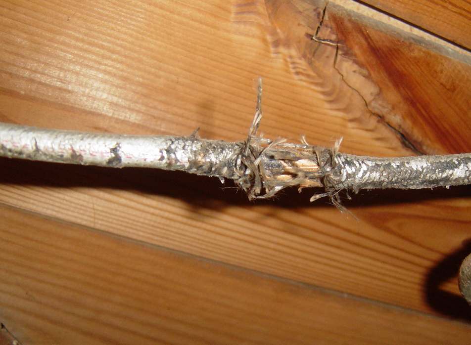 Older cloth-covered wiring with damaged insulation. If all devices on a circuit are turned off or unplugged, there should be no electricity used. Similarly if the main circuit breaker for a home is turned off the electric meter should not spin. These would be indicators of problematic leakage and should be investigated by an electrician. Electrical Arcing Electrical arcing is a potentially dangerous situation caused by loose connections, missing insulation on wires, etc. The problem can be in the home's wiring or in a faulty device. Arc fault circuit breakers can detect current leakage through arcs. This type of leakage can be a safety hazard. 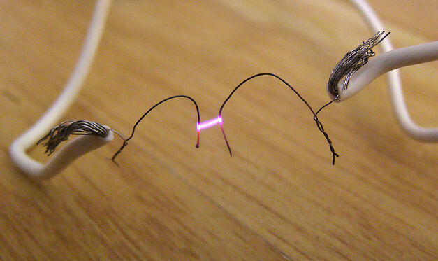 Electrical arcing between two exposed wires. Voltage Drop Voltage drop happens when voltage is lost through the circuit, resulting in lower voltage at the end of the run. Voltage is lost when cables are too long or too small to handle the electrical current load. Too much voltage drop can cause devices to not work properly, like flickering lights or weak motors. This can lead to premature equipment failure and hazardous situations. Under normal circumstance, the lower voltage also results in a correspondingly higher current draw. Thus, the same device positioned near the electric panel will cost less to operate than if a long extension cord is used. For the most people, this loss is so small it is just not worth worrying about. Phantom Power "Phantom" or "vampire" power is used by many electronics. Expecting a remote control to turn on your TV requires constant power to be fed to the TV. Indicator lights use power even when a device is off. This type of electrical usage is sometimes considered leakage. It can be somewhat controlled by the homeowner. One good way is the usage of smart power strips, which completely shuts off power to unused devices. There are a few different types and there is a nice description here: https://www.nrel.gov/docs/fy14osti/60461.pdf. 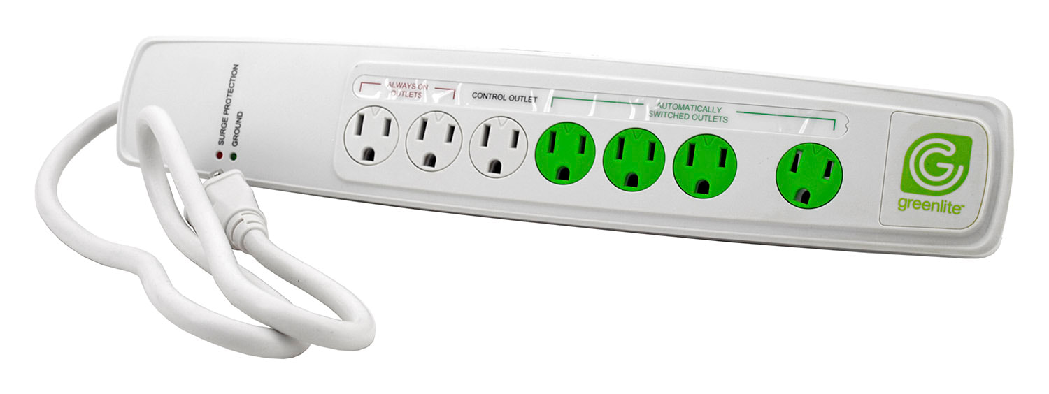 One type of smart power strip. Faulty Device A device could use more amperage than expected. Older devices may build up resistance in the wiring which causes greater electric usage. Unless the device has a large draw (large motor, air conditioner, water heater, refrigerator, etc.), this may not be worth your attention. These can be checked using a device like Kill A Watt meter. 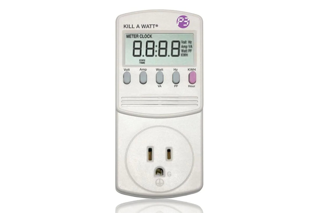 Kill A Watt Meter Usage Factors Anyone who steps back to take a look at the bigger picture will notice that electrical usage has been dramatically increased through the years. The average U.S. home in 1950 was 1000 SF. Now we are building single-family homes in excess of 2300 SF. This more than doubling of home size comes with a consequent increase in electrical usage.
While a large modern television uses more power than older CRT tube TVs, we now have many TVs instead of just one. The 1950s TV used no power when turned off. The same was true of stereos and radios. The "modern" home may have 40-50 electronic devices. Many devices are using constant phantom power and others, routers for example, are left on at all times. The average home also uses more lighting electricity. LEDs use perhaps 10% of the electricity that incandescent bulbs did. But now we regularly leave lights on when we leave the room. It is not uncommon to find homes where the owners leave lights on at night and when not at home. In short, while we used to light the room we were in, we are now leaving lights on for convenience. So perhaps this is food for thought for some of us. An energy audit is an assessment of your home as it relates to energy usage. We consider your entire home, assessing energy usage and potential improvements. The following items are included in an audit: 1. We sit with you to discuss your home and energy usage, past and present. 2. We review energy bills to note patterns and discrepancies. 3. We perform diagnostic tests of your home and HVAC system. 4. We visually inspect your home, including the exterior, attic and basement. 5. We compile a written report identifying the most significant findings. Our recommendations are prioritized, with our top recommendations based on what we feel offer the highest potential savings. 6. You can then implement these recommendations, resulting in energy savings and a more comfortable home. Perhaps the most revealing portion of our test is an infiltration test. This test determines how leaky your home is. The easier that air escapes from your home, the more it costs you. We combine this test with a thermal imaging camera, allowing us to identify air leaks, missing insulation and sometimes even moisture, hidden behind your walls and ceilings. 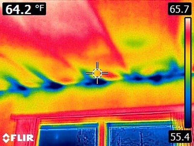 More insulation is not always the best solution. Insulation performs like a fluffy sweater while air-sealing is like a windbreaker for the home. Think of wearing only a sweater on a cold, breezy winter day. Would you add another sweater, or a windbreaker? Perhaps both, given the choice, but forced to choose, the windbreaker makes a bigger difference. The same is true of your home. 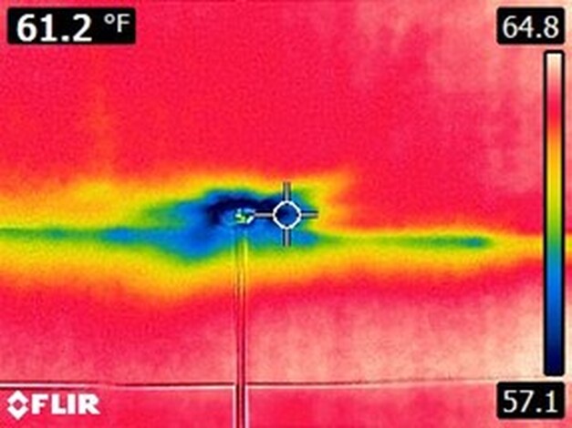 Windows are rarely the best solution. While you might feel a draft there, even the best new window is still a hole in the wall. New windows might help --- but they rarely pay for themselves. 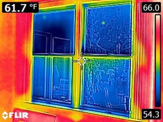 In the end we'll leave you with many suggestions and a written report of the things which will make the biggest difference for energy usage in your home. So why wait? The cost of an audit is small compared with the energy losses you may have. Why Do Townhouses Keep Failing Blower Door Tests?Energy Auditors, LLC has been doing blower door tests on new homes for over 10 years and it is common knowledge that townhouses and duplexes tend to perform more poorly than single-family homes. But why is that? We have done some research to get to the bottom of this. We are indebted to Robby Schwarz, founder of BUILDTank, Inc., for much of information below. A link to his research can be found at the end of the article. The IssueThe most common type of adiabatic wall used in new construction homes today was designed generally to optimize fire safety rather than air tightness. While fire safety is clearly important, air tightness is becoming increasingly important as the energy code has become more strict in the last few years. Shaft walls are frequently constructed with metal “C” and “H” channels holding drywall two thick sheets of drywall. This forms a relatively air-tight, continuous shaft completely separating the two homes. The adiabatic walls are then typically finished by installing a 2x4 wall on each side of the shaft wall. Drywall is installed on the 2x4 wall. A ¾” gap is left between the finish wall framing and the shaft wall to prevent heat transfer in the event of a fire. 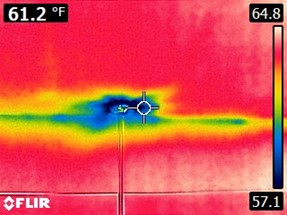 The problem is that this gap is usually open to the attic, allowing unconditioned air to enter the interior wall. This means that the vast majority of the air leakage at the adiabatic walls is not coming through the walls from the adjacent unit, but into the wall assembly around the perimeter edge of the principal townhouse unit. In order to effectively air-seal the wall, this gap must be addressed. Complicating the situation is that some code officials do not permit any air sealing of adiabatic walls because they believe it could reduce the effectiveness of the fire safety measures. This makes the typical air-sealing solution unavailable, and as a result, these townhomes may have trouble passing an air infiltration test for energy code compliance. Typical Solution: How to Air Seal Shaft WallsIndustry experts have determined that sealing the perimeter edge of the shaft wall at this ¾" gap is the key to sealing these adiabatic walls. Spray foam is typically used for a sealant. Where the shaft wall is constructed with “C” channels back-to-back, those seams should be sealed with caulk. This method should dramatically reduce adiabatic wall leakage. It requires copious amounts of spray foam due to the size of the gaps, but is a simple solution to perform. We recommend verifying the insulator's work as it is all too common for this task to be done hurriedly and with too little sealant. 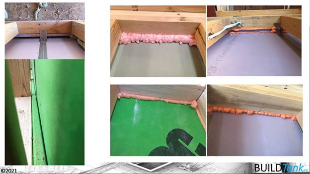 AeroBarrier Solution and Its Effect on TownhomesAeroBarrier is a new technology that works by pressurizing the home and spraying an aerosolized sealant throughout the interior. The pressure forces the sealant to flow through holes in the air barrier which causes the sealant to coagulate and seal the holes. This procedure must be done right after the drywall is installed in the home. During the application process, the fan and sprayers can be run for as long as needed to achieve the level of tightness the builder desires. The longer the system runs, the tighter the home gets, assuring that the home will be able to meet air infiltration requirements. AeroBarrier works by sealing the Red Interior Air Barrier line shown below.AeroBarrier is a new technology that works by pressurizing the home and spraying an aerosolized sealant throughout the interior. The pressure forces the sealant to flow through holes in the air barrier which causes the sealant to coagulate and seal the holes. This procedure must be done right after the drywall is installed in the home. During the application process, the fan and sprayers can be run for as long as needed to achieve the level of tightness the builder desires. The longer the system runs, the tighter the home gets, assuring that the home will be able to meet air infiltration requirements. AeroBarrier works by sealing the Red Interior Air Barrier shown below. 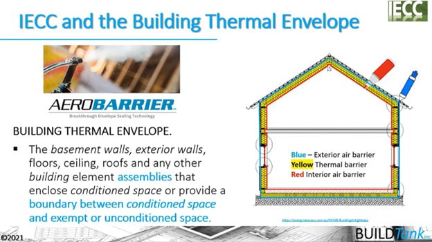 A common misconception is that a row of townhomes can be air-sealed by having AeroBarrier applied to every other dwelling unit, but one builder found that this is not the case. Sealing every other unit did very little to improve the blower-door scores in the unsealed units but sealing all units in the row dramatically improved the scores (See graphic below). This helps to prove that the primary pathway for adiabatic wall leakage is not from unit to unit, but from each unit individually through the shaft wall system itself. 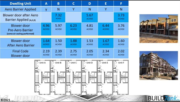 Alternative Shaft Wall Construction MethodsIt seems as though the current adiabatic wall design is not the most intuitive since its design ignores air sealing. But there are many other approved shaft wall designs that are more efficient from an energy standpoint and a material cost standpoint. Construction methods, load capacity, R-value and sound transmission may also need to be considered. One example is the UL 341 (or U341) which consists of two 2x4 walls with drywall on both sides of each individual wall and a 1” gap in between the walls. 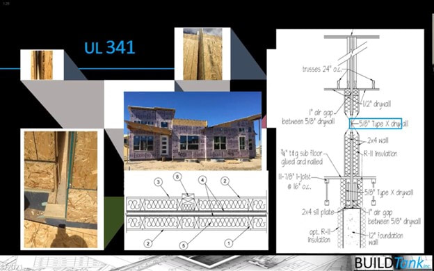 Another method is UL 350 which is similar to UL 341 but has a new product called LP Flame Block in the center instead of drywall. It also uses resilient channel between the framing and drywall for a higher STC rating. 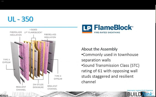 UL 382 is a proprietary design featuring two 2x4 walls with a 1” gap in between and the walls are filled with Nu-Wool's WALLSEAL fire and sound insulation. 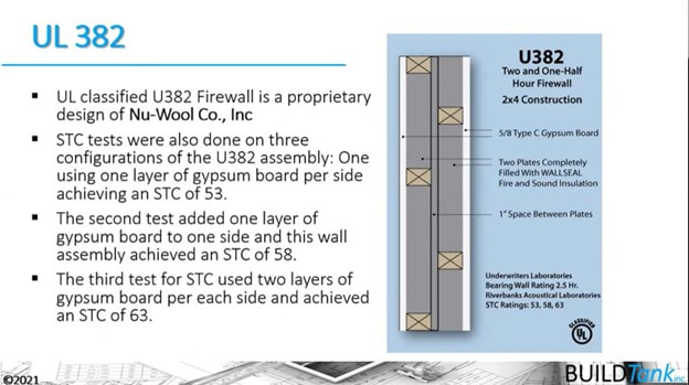 UL 370 is built with two staggered rows of 16" o.c. 2x4 studs that are spaced 2 ¼“ apart and the whole cavity including the stud rows and the gap in between, is filled with cellulose. UL 370 would provide the greatest insulation R-value out of all these options. 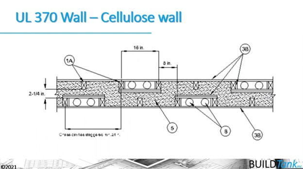 ConclusionThere are multiple ways to air seal townhouses enough to satisfy the energy code without forfeiting fire safety. As noted, there are many considerations in choosing a wall system and many good options other than the one most commonly used. Each of these options has pros and cons. Of those discussed here, AeroBarrier is likely the simplest method. Manually air sealing shaft walls can be effective as long as fire safety is taken into account. Air sealing alternative shaft wall designs such as UL 341 and UL 350 would be basically the same as the standard design, while UL 382 and UL 370 might look a little different. No matter what method you choose, it can be done effectively, and Energy Auditors LLC is ready to help you do it. Works Cited
Robby Schwarz. “Creating an Airtight Shaft Liner Area Separation Wall” Build Tank Inc. resnet2022.virtualbyvario.com/vod/nzc-15-creating-an-airtight-shaft-liner-area-separation-wall/ Fire sprinklers, when required by the building code, can result in many penetrations in the building envelope, in turn leading to a lot of air leakage. Currently the building code in Pennsylvania requires fire sprinklers for multi-family dwellings. Maryland requires them for all new homes. In most cases --- light fixtures, smoke alarms, etc. --- when a penetration is made through the ceiling, the penetration can be sealed with foam or caulk. Fire sprinklers are not so simple. Most sprinklers we see sit nearly flush with the ceiling drywall and require a hole to be cut in the drywall for the body of the sprinkler. 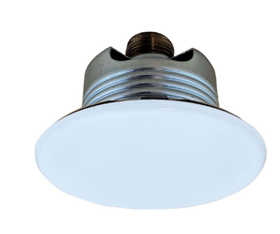 The top of the sprinkler, inside the ceiling has large holes which will necessarily leak air into the home through the housing and the plastic plate. 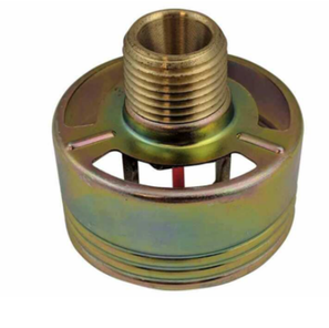 It would seem that the sprinkler could be sealed to the drywall around the perimeter. However, the IECC Energy Code specifically says "Where required to be sealed, concealed fire sprinklers shall only be sealed in a manner that is recommended by the manufacturer. Caulking or other adhesive sealants shall not be used to fill voids between fire sprinkler cover plates and walls or ceilings." And it is not hard to see that even if the sprinkler were sealed to the drywall, air would still leak directly through the unit. Foaming the entire unit is not practical and likely would not be a viable option. Sprinkler manufacturers typically do not mention air sealing at all, except to suggest avoiding foam or caulk. So, what can be done? An air space must be maintained around the sprinkler for it to work properly. It can't be sealed directly to the drywall, nor foamed over. But we want to prevent airflow from the interior conditioned space, through the fire sprinkler and into the attic or other unconditioned space. Here are some possibilities: Option 1. Bring the sprinklers systems within the building envelope, using dropped soffits, interior walls and floors. Commercial buildings commonly use an interstitial space for ductwork and mechanicals. The same approach would work on the top floor of a residence, by adding an 8 to 12" false ceiling space. An added benefit is that ductwork and other mechanicals could also be run inside this space. (Credit should go to Abe Kruger for this idea: http://www.homeenergy.org/show/article/nav/trends/id/1775) 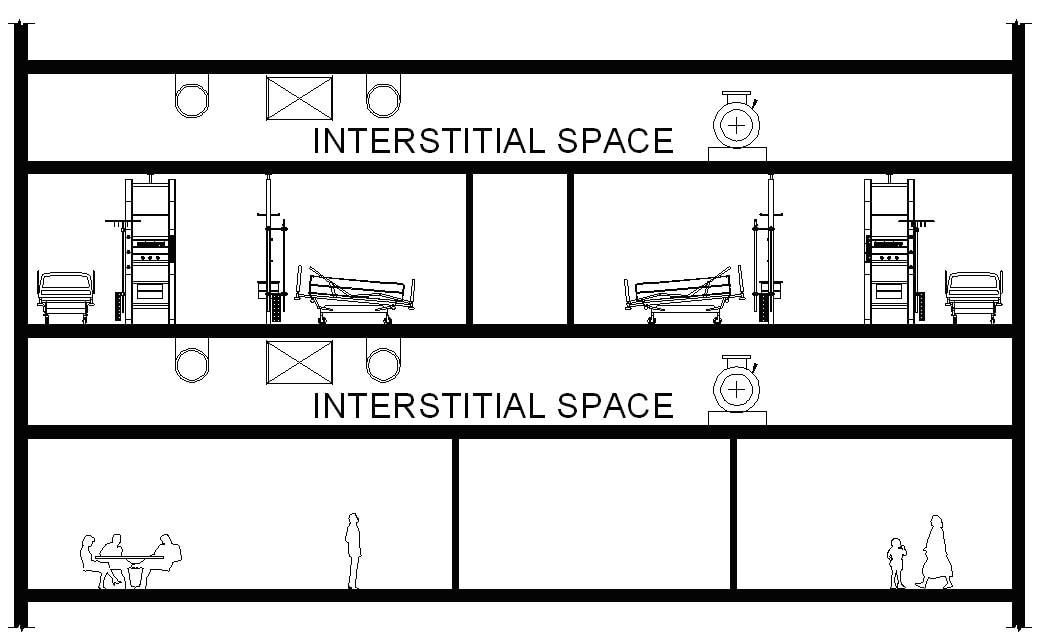 Option 2: Box over each sprinkler head with rigid foam sealed to the drywall and to the pipes. This is similar to the practice of boxing in recessed can lights when they are not rated for insulation contact. The key here is getting the boxes sealed tightly to the drywall and to the pipes. We would recommend confirming your approach with the building code official beforehand.
Option 3: Install fire sprinklers with a sealed gasket. These are available for hospitals and other situations where a tight seal is necessary. Here is one type: https://www.qrfs.com/fire-sprinklers/tyco-air-and-dust-seal-rfii-fire-sprinklers-56-908-1-001 The third option seems simplest, but we have not calculated a cost comparison. There might be other ways to approach this problem that we haven't considered; please feel free to suggest alternatives. We'd certainly like to see these tightened up so that builders do not struggle to pass infiltration tests and future homeowners aren't forced to accept this air leakage. Higher air leakage results in a corresponding decline in comfort and energy efficiency. 1. Attic knee-walls. Installing an air barrier on the attic side of the wall helps tremendously. Rigid foam is commonly used, but other materials will work if insulation requirements are already met. Spray foam or sealant should be used to seal all edges and joints. The barrier needs to extend into the joist spaces below the knee walls. These joist spaces often allow massive air leakage.  2. Adiabatic walls, aka common or party walls. These walls can also leak a lot of air, both from the outside and from the next unit. Infiltration tests do not differentiate the source of air. Unwanted odors, microorganisms and other airborne particles should be kept out, regardless of the source. It is best to devise a plan beforehand for air-sealing these common walls. This plan should take into account the specific construction details. 3. Ceilings. Seal all penetrations for lights, wires etc. through the ceilings, and also seal the top plates. See Common sources of air leakage, Part 1 for more detail. 4. Bottom plates on slab. Make sure the slab is free of dust and moisture before sealing the bottom plate to slab. Also be sure not to skimp on the sealant. Please see Slabs: in Common sources of air leakage, Part 3 for more detail. There is much crossover between air leakage in townhomes and single family dwellings. Common walls are the unique element and we'll plan to address these in more detail in a future post. Thanks! Rim joists & sill plates: These are often significant sources of air leakage as air escapes through the framing and into the home. 1. Sill plates. Sill seal is not an effective air block. This applies to all homes, but is particularly important for slab models.
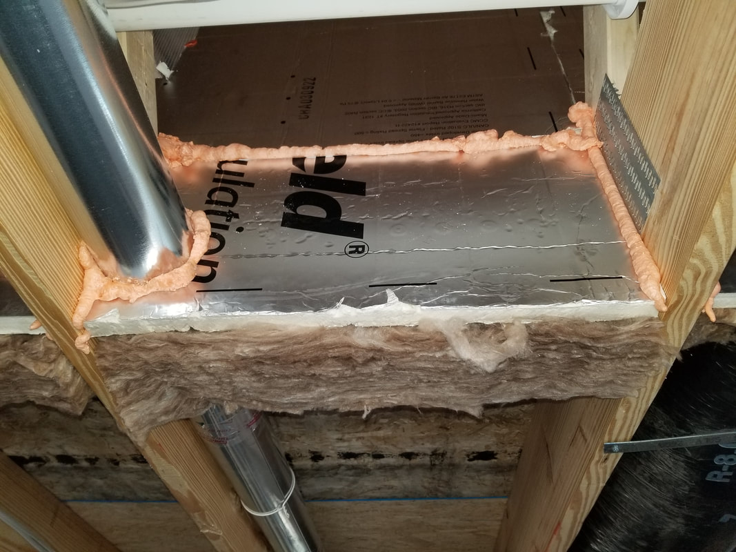
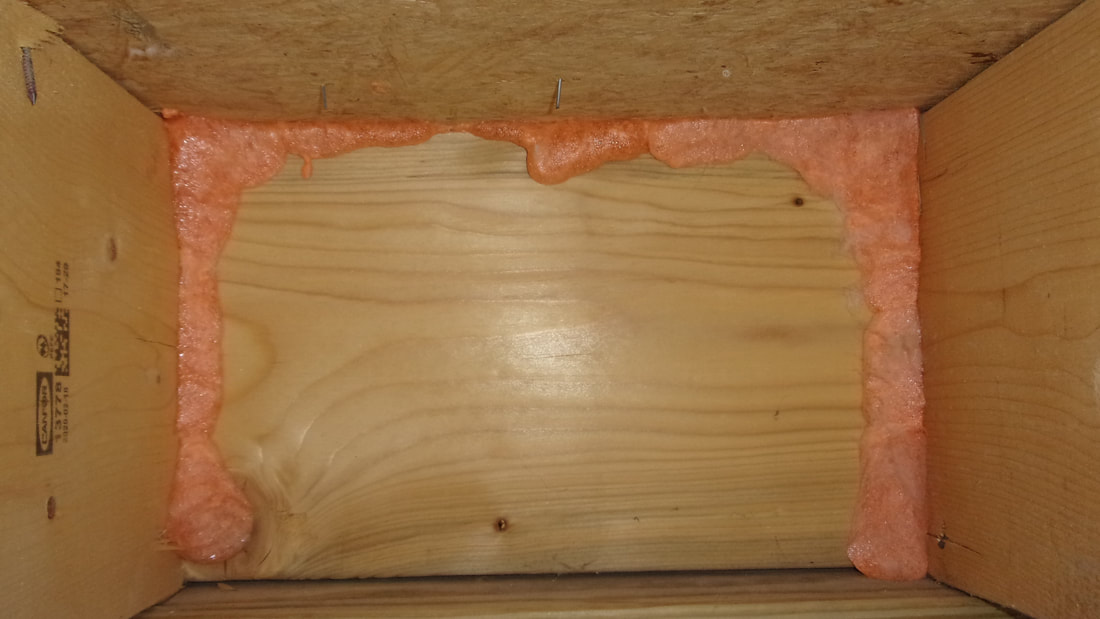 Note that sealant was not applied on the bottom joint. 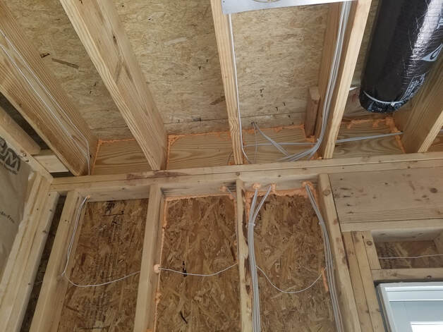 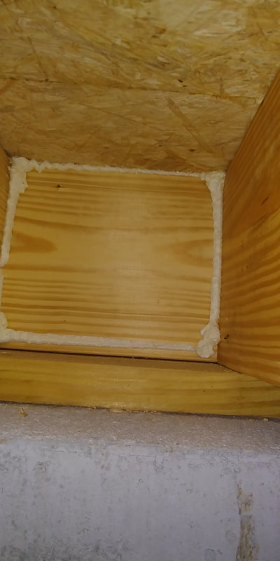 Foam missed the lower joint and is incomplete at the top. Walls: Typically we try to prevent unconditioned air from getting into the walls. Air is often observed coming out of the electrical devices, but this is a symptom, not the cause. 1. Rim joists, doors and windows, see above, see above and previous post. 2. Penetrations to the exterior should be sealed. 3. Penetrations through the top plates to unconditioned spaces (attics, basements) should be sealed. 4. Walls adjacent to unconditioned floor space.
Basements & Crawlspaces: 1. Rim joists, sill plates, doors and windows, see above and previous post. 2. Penetrations through the wall. 3. Penetrations through the floor slab. While typically less air leaks through a hole cut in the slab, this is often a source of air flow into the home. For a tight home, seal around penetrations and fill larger cuts with concrete. Slabs: 1. When wall framing rests on a slab, it is critical that these be sealed well. All too often these are done sloppily and sealant does not completely seal. Dirt and debris and protruding sill seal should be removed first. A heavy bead of caulk is generally more effective than spray foam. Tool the caulk to ensure good adhesion to both surfaces. 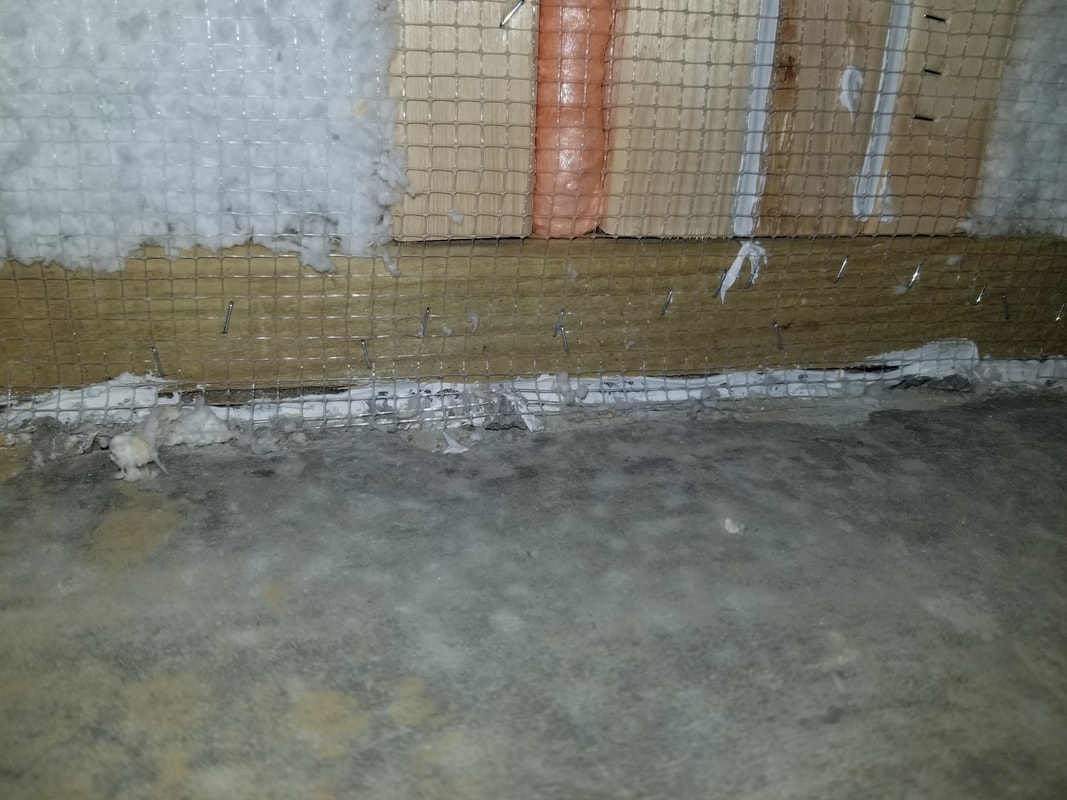 Insufficient caulk does a poor job stopping air flow. We hope these tips were helpful to you. Please let us know if you have questions.
Attics, continued: Quite often, the greatest source of air leakage and energy loss in homes is the attic. These are some additional ways that conditioned air can leak from the home into the attic: 5. Chases for plumbing, electric, HVAC, etc.
 9. Bonus rooms. Truss packages which lack bottom plates leave a gap between the drywall and the floor sheathing.
Doors & Windows: While potentially leaky, doors and windows are surprisingly easy to deal with in a new home. 1. Gaps between framing and doors & windows.
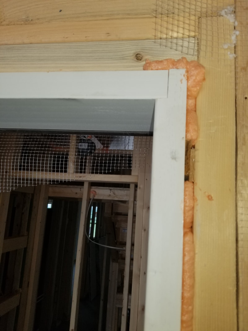 Note the gaps around the shims which are not air sealed. Foam does not appear to continue above the frame, although it may be caulked. 2. Installation must be level and square. Any doors or windows which do not open and shut properly can often be instances of poor installation. Not only are these difficult to operate, they do not seal as well as the manufacturer intended.
3. Gaps under doors.
Thanks for reading. We'll have more suggestions in Part 3. |
Archives
August 2023
Categories |
 RSS Feed
|
|

|

|

|

|

|
© 2015-2022 - Energy Auditors, LLC - All Rights Reserved (717) 914-8155 - [email protected] - Dillsburg, PA